Free CompTIA N10-009 Practice Questions 2026 - Page 20

An employee in a corporate office clicks on a link in an email that was forwarded to them. The employee is redirected to a splash page that says the page is restricted. Which of the following security solutions is most likely in place?
A. DLP
B. Captive portal
C. Content filtering
D. DNS sinkholing
Explanation:
An employee in a corporate office clicks on a link in an email that was forwarded to them and is redirected to a splash page stating the page is restricted. This behavior suggests a security mechanism is blocking access to the linked content. The most likely security solution in place is content filtering.
C. Content filtering:
How it works: Content filtering is a security solution that monitors and controls web traffic based on URL categories, keywords, or specific sites. When a user attempts to access a restricted or potentially malicious site (e.g., phishing or malware), the filter blocks the request and often displays a splash page indicating the restriction.
Why it fits: the employee clicking a link in a forwarded email likely triggered a content filter, which recognized the destination as restricted (e.g., a known phishing site). The splash page is a typical response from content filtering systems (e.g., Cisco Umbrella, Fortinet FortiGuard), informing the user of the block, aligning with corporate security policies to prevent malware or data leaks.
Context: This is a common practice in corporate environments to protect against email-based threats, especially during peak office hours.
Why Not the Other Options?
A. DLP (Data Loss Prevention):
DLP monitors and prevents unauthorized data exfiltration (e.g., sensitive files leaving the network). While it might block certain actions, it typically doesn’t redirect to a splash page for web links unless integrated with content filtering, making it less likely as the primary solution here.
B. Captive portal:
A captive portal requires users to authenticate (e.g., with credentials) before accessing a network or internet, often seen in public Wi-Fi. It doesn’t typically block specific web links with a restriction splash page unless misconfigured, which is not the norm for this scenario.
D. DNS sinkholing:
DNS sinkholing redirects malicious domain requests to a null or controlled IP address to block access. While it can prevent access to harmful sites, it usually doesn’t display a splash page indicating the page is restricted, as the request is silently redirected, making it less likely.
Why Content Filtering?
The presence of a splash page stating the page is restricted is a hallmark of content filtering, which actively blocks and notifies users about restricted web content. This fits the scenario where an email link triggered a security response, likely due to the site being categorized as unsafe, a common corporate defense against phishing attacks.
Reference:
CompTIA Network+ (N10-009) Exam Objectives:
Section 3.3 – "Given a scenario, implement secure network configurations." This includes understanding content filtering for web security.
RFC 3234 (Middleboxes):
Discusses content filtering as a network security mechanism.
Cisco Secure Web Gateway Guides:
Detail splash page responses for blocked content.
A network engineer is now in charge of all SNMP management in the organization. The engineer must use a SNMP version that does not utilize plaintext data. Which of the following is the minimum version of SNMP that supports this requirement?
A. v1
B. v2c
C. v2u
D. v3
Explanation:
A network engineer is now in charge of all SNMP (Simple Network Management Protocol) management in the organization and must use a version that does not utilize plaintext data, requiring encryption and secure authentication. The minimum version of SNMP that supports this requirement is v3.
D. v3:
How it works: SNMPv3 introduces security features including authentication, integrity, and encryption. It uses protocols like HMAC-SHA for authentication and AES or DES for encryption, ensuring that data (e.g., SNMP messages) is not transmitted in plaintext. It also supports user-based security models (USM) with credentials.
Why it fits: the requirement to avoid plaintext data necessitates a version with encryption. SNMPv3 is the first and only version to provide this capability, making it the minimum version that meets the organization’s security needs. For example, the engineer could configure SNMPv3 with an AES-128 cipher to protect sensitive network data.
Context: This is critical for modern enterprise networks where plaintext SNMP (as in v1 and v2c) poses significant security risks due to eavesdropping vulnerabilities.
Why Not the Other Options?
A. v1:
SNMPv1 uses community strings sent in plaintext, offering no encryption or authentication beyond basic access control. It is highly insecure and does not meet the requirement.
B. v2c:
SNMPv2c improves performance with GetBulk requests but still relies on plaintext community strings for authentication, lacking encryption. It is also insecure for sensitive data transmission.
C. v2u:
SNMPv2u (User-based) was a proposed enhancement to v2c with user-based authentication, but it was never widely adopted and does not include encryption. It is not a standard version, and its security is insufficient compared to v3.
Why v3?
SNMPv3 is the minimum version that addresses the plaintext issue by providing encryption and authentication, ensuring that SNMP data is protected against interception. This aligns with the engineer’s responsibility to secure SNMP management across the organization, making it the only viable choice.
Implementation Considerations:
Configure SNMPv3 on all managed devices with unique usernames.
Set up authentication (e.g., SHA) and encryption (e.g., AES) protocols.
Define access control lists (ACLs) for authorized users.
Test SNMPv3 queries (e.g., snmpget -v3) to verify secure communication.
Update the SNMP manager (e.g., Nagios, SolarWinds) to support v3.
Reference:
CompTIA Network+ (N10-009) Exam Objectives:
Section 1.5 – "Compare and contrast common network protocols and their functions." This includes understanding SNMP versions and security.
RFC 3414 (SNMPv3 User-based Security Model):
Details v3’s encryption and authentication features.
Cisco SNMP Configuration Guides:
Recommend v3 for secure management.
A network administrator needs to fail over services to an off-site environment. This process will take four weeks to become fully operational. Which of the following DR (Disaster Recovery) concepts does this describe?
A. Hot site
B. Warm site
C. Cold site
D. Active-active approach
Explanation:
A network administrator needs to fail over services to an off-site environment, and this process will take four weeks to become fully operational. This scenario aligns with the cold site concept in disaster recovery (DR).
C. Cold site:
How it works: A cold site is an off-site facility equipped with basic infrastructure (e.g., power, cooling, space) but lacking pre-installed hardware, software, or data. It requires significant setup time and effort to become operational, often involving the installation and configuration of servers, networking equipment, and data restoration.
Why it fits: the four-week timeline to achieve full operability indicates a cold site. This duration allows for procuring equipment, setting up the network, and restoring data, which is typical for a cold site that starts with minimal resources and requires manual preparation post-disaster.
Context: Cold sites are cost-effective for organizations with longer recovery time objectives (RTOs) and are suitable when immediate service restoration is not critical.
Why Not the Other Options?
A. Hot site: A hot site is a fully operational off-site facility with pre-installed hardware, software, and up-to-date data, enabling near-instant failover (e.g., minutes to hours). A four-week recovery period is far too long for a hot site, which is designed for rapid restoration.
B. Warm site: A warm site has partial infrastructure (e.g., pre-installed servers, partial data backups) and can be operational in days to a week with additional setup. A four-week timeline exceeds the typical warm site recovery period, making it less likely.
D. Active-active approach: An active-active approach involves two live data centers running simultaneously, with failover occurring almost instantly if one fails. This doesn’t match the four-week setup process, as it implies pre-existing operational redundancy, not a post-disaster recovery.
Why Cold Site?
The four-week duration to become fully operational is characteristic of a cold site, where the focus is on cost savings and longer recovery times. The administrator would need to plan for equipment deployment, network configuration, and data restoration, aligning with the cold site’s minimal initial state.
Implementation Considerations:
Verify the cold site’s basic infrastructure (e.g., power, space).
Procure and install necessary hardware and networking equipment.
Restore data from backups (e.g., off-site tapes or cloud storage).
Test network connectivity and service functionality.
Document the recovery process for future improvements.
Reference:
CompTIA Network+ (N10-009) Exam Objectives:
Section 3.4 – "Explain disaster recovery and high availability concepts." This includes understanding cold site characteristics.
NIST SP 800-34:
Defines cold sites as facilities with long RTOs due to setup needs.
Cisco DR Planning Guides:
Describe cold sites for extended recovery scenarios.
A network engineer needs to virtualize network services, including a router at a remote branch location. Which of the following solutions meets the requirements?
A. NFV
B. VRF
C. VLAN
D. VPC
Explanation:
A network engineer needs to virtualize network services, including a router at a remote branch location, requiring a solution that supports the virtualization of network functions. The best solution is NFV (Network Functions Virtualization).
A. NFV:
How it works: NFV is a technology that virtualizes network services, such as routers, firewalls, or switches, by running them as software instances on standard hardware (e.g., x86 servers) using virtualization platforms like VMware or KVM. It leverages Network Function Virtualization Infrastructure (NFVI) to deploy these services dynamically.
Why it fits: At 10:28 AM PKT on Thursday, August 21, 2025, the requirement to virtualize a router at a remote branch location aligns with NFV. Instead of deploying physical hardware, the engineer can use NFV to run a virtual router (e.g., a virtualized Cisco CSR 1000V) on a server at the branch, reducing costs and enabling centralized management. This is ideal for remote sites where physical infrastructure might be limited.
Context: NFV is widely adopted in modern networks to enhance flexibility and scalability, especially for branch deployments.
Why Not the Other Options?
B. VRF (Virtual Routing and Forwarding):
VRF is a technology that creates multiple virtual routing tables within a single physical router, enabling network segmentation. While it virtualizes routing instances, it does not virtualize the router itself or other network services, making it insufficient for the full virtualization requirement.
C. VLAN (Virtual Local Area Network):
VLANs segment a physical network into multiple logical networks at Layer 2 using 802.1Q tagging. They enhance security and organization but do not virtualize network services like a router, limiting their relevance here.
D. VPC (Virtual Private Cloud):
A VPC is a cloud service (e.g., AWS VPC) that provides a isolated virtual network within a public cloud. While it supports virtualized networking, it is specific to cloud environments and not designed for on-premises router virtualization at a remote branch.
Why NFV?
NFV meets the need to virtualize network services, including a router, by allowing the engineer to deploy a virtualized router on commodity hardware at the remote branch. This approach supports centralized control, rapid deployment, and cost efficiency, making it the most suitable solution for the scenario.
Implementation Considerations:
Select an NFV platform (e.g., OpenStack, VMware NSX).
Deploy a virtual router image (e.g., Cisco CSR, Juniper vMX) on the branch server.
Configure NFVI to manage the virtual router and other services.
Ensure network connectivity and test routing functionality.
Monitor performance and adjust resource allocation as needed.
Reference:
CompTIA Network+ (N10-009) Exam Objectives:
Section 2.5 – "Explain common virtualization and cloud concepts." This includes understanding NFV for network service virtualization.
ETSI NFV White Paper:
Defines NFV for virtualizing network functions like routers.
Cisco NFV Deployment Guides:
Detail virtual router implementation at branch locations.
A company's network is experiencing high latency and packet loss during peak hours. Network monitoring tools show increased traffic on a switch. Which of the following should a network technician implement to reduce the network congestion and improve performance?
A. Load balancing
B. Port mirroring
C. Quality of Service
D. Spanning Tree Protocol
Explanation:
A company's network is experiencing high latency and packet loss during peak hours, with network monitoring tools showing increased traffic on a switch. To reduce network congestion and improve performance, the network technician should implement Quality of Service (QoS).
C. Quality of Service:
How it works: QoS is a set of techniques that prioritizes network traffic based on application, user, or data type. It manages bandwidth allocation, reduces latency, and minimizes packet loss by assigning priority to critical traffic (e.g., VoIP, video) and limiting less important traffic during congestion.
Why it fits: peak hours likely coincide with high traffic volumes on the switch, causing latency and packet loss. QoS can mitigate this by prioritizing essential applications (e.g., business calls) over less critical traffic (e.g., file downloads), optimizing performance without requiring hardware upgrades. For example, the technician could configure QoS to prioritize UDP traffic on port 5060 for VoIP.
Context: This is a common solution for networks experiencing congestion during high-usage periods, especially in enterprise environments.
Why Not the Other Options?
A. Load balancing:
Load balancing distributes traffic across multiple devices or links to prevent overload on a single resource. While it can reduce congestion, it requires additional hardware (e.g., a second switch or link), which may not be feasible or immediately address the switch’s current traffic issue without further investment.
B. Port mirroring:
Port mirroring copies traffic from one switch port to another for monitoring or troubleshooting (e.g., with a packet analyzer). It helps diagnose the problem but does not reduce congestion or improve performance directly.
D. Spanning Tree Protocol (STP):
STP prevents switching loops by blocking redundant paths, ensuring network stability. However, it doesn’t address congestion or latency caused by high traffic volumes, making it irrelevant to the performance issue.
Why Quality of Service?
QoS is the most effective solution for managing existing congestion on the switch during peak hours. By prioritizing traffic and shaping bandwidth, it directly reduces latency and packet loss, improving network performance without requiring immediate infrastructure changes, which aligns with the technician’s goal.
Implementation Considerations:
Identify critical applications (e.g., VoIP, video) and their ports/protocols.
Configure QoS on the switch (e.g., set DSCP values like EF for expedited forwarding).
Apply traffic shaping or policing to limit non-essential traffic.
Test performance during peak hours to verify improvements.
Monitor and adjust QoS policies based on usage patterns.
Reference:
CompTIA Network+ (N10-009) Exam Objectives:
Section 2.4 – "Explain common configuration concepts." This includes implementing QoS to manage congestion.
RFC 4594 (Configuration Guidelines for DiffServ Service Classes):
Details QoS for prioritizing traffic.
Cisco QoS Configuration Guides:
Recommend QoS for latency and packet loss mitigation.
Which of the following is a company most likely enacting if an accountant for the company can only see the financial department's shared folders?
A. General Data Protection Regulation
B. Least privilege network access
C. Acceptable use policy
D. End user license agreement
Explanation:
If an accountant for a company can only see the financial department's shared folders, the company is most likely enacting least privilege network access.
B. Least privilege network access:
How it works: The principle of least privilege (PoLP) restricts user access rights to the minimum necessary for their job function. In this case, the accountant’s permissions are limited to the financial department’s shared folders, preventing access to unrelated data (e.g., HR or marketing files).
Why it fits: this restriction indicates the company has implemented a security policy to ensure employees, including the accountant, only access resources relevant to their role. This reduces the risk of unauthorized data exposure or misuse, a common practice in enterprise network security.
Context: This is a standard security measure aligned with frameworks like NIST or ISO 27001, often enforced via Active Directory or similar access control systems.
Why Not the Other Options?
A. General Data Protection Regulation (GDPR):
GDPR is a European regulation mandating data protection and privacy for EU citizens, including rights to access and erase data. While it may influence access policies, it doesn’t specifically dictate that an accountant sees only financial folders; it’s a broader compliance framework, not the direct action here.
C. Acceptable use policy (AUP):
An AUP outlines rules for using company resources (e.g., no personal use of the network), but it doesn’t enforce specific access restrictions like limiting folder visibility. It’s a guideline, not a technical access control mechanism.
D. End user license agreement (EULA):
A EULA is a legal contract between a user and software vendor, governing software use (e.g., terms for Microsoft Office). It has no bearing on network folder access permissions within a company.
Why Least Privilege Network Access?
The scenario describes a specific access limitation based on the accountant’s role, which is the hallmark of least privilege. This security principle ensures that only necessary data is accessible, minimizing the attack surface and aligning with the company’s likely intent to protect sensitive information.
Reference:
CompTIA Network+ (N10-009) Exam Objectives:
Section 3.3 – "Given a scenario, implement secure network configurations." This includes understanding least privilege principles.
NIST SP 800-53:
Recommends least privilege for access control.
Microsoft Active Directory Guides:
Detail role-based access control for least privilege implementation.
Which of the followingportscreates asecure connectionto adirectory service?
A. 22
B. 389
C. 445
D. 636
Explanation:
The question asks which port creates a secure connection to a directory service, requiring a port associated with a secure protocol for directory access. The correct answer is 636.
D. 636:
How it works: Port 636 is used by LDAPS (LDAP over SSL/TLS), a secure version of the Lightweight Directory Access Protocol (LDAP). It encrypts communication between clients and directory services (e.g., Active Directory) using SSL/TLS, ensuring confidentiality and integrity of data such as user credentials.
Why it fits: a secure connection to a directory service like Active Directory or OpenLDAP requires encryption to protect sensitive information. Port 636 is the standard IANA-assigned port for LDAPS, making it the appropriate choice for secure directory access.
Context: This is commonly used in enterprise environments to secure authentication and directory queries over untrusted networks.
Why Not the Other Options?
A. 22:
Port 22 is used by SSH (Secure Shell) for secure remote access to devices or servers. While it provides a secure connection, it is not specific to directory services, which are handled by LDAP-based protocols.
B. 389:
Port 389 is the default port for unencrypted LDAP, used for directory service queries without security. It does not create a secure connection, making it unsuitable for the requirement.
C. 445:
Port 445 is used by SMB (Server Message Block) for file and printer sharing in Windows environments. It can be secured with encryption (e.g., SMB 3.0), but it is not a directory service port and is not primarily designed for that purpose.
Why 636?
Port 636 is specifically designated for LDAPS, providing a secure, encrypted channel to directory services. This ensures that directory operations, which often involve sensitive data, are protected against eavesdropping, aligning with the need for a secure connection.
Reference:
CompTIA Network+ (N10-009) Exam Objectives:
Section 1.5 – "Compare and contrast common network protocols and their functions." This includes understanding secure directory ports like 636.
IANA Service Name and Transport Protocol Port Number Registry:
Assigns port 636 to LDAPS.
RFC 4511 (LDAP: The Protocol):
Describes LDAPS and its use of port 636.
A network administrator is notified that a user cannot access resources on the network. The network administrator checks the physical connections to the workstation labeled User 3 and sees the Ethernet is properly connected. However, the network interface’s indicator lights are not blinking on either the computer or the switch. Which of the following Is the most likely cause?
A. Theswitch failed.
B. Thedefault gateway is wrong.
C. Theport Is shut down.
D. TheVLAN assignment is incorrect
Explanation:
A network administrator is notified that a user cannot access resources on the network, specifically at User 3’s workstation. The administrator checks the physical connections and sees the Ethernet cable is properly connected, but the network interface’s indicator lights are not blinking on either the computer or the switch. The most likely cause, is the port is shut down.
C. The port is shut down:
How it works: On a managed switch, an administrator can administratively shut down a port (e.g., using a command like shutdown on Cisco devices), disabling all traffic on that port. This stops link establishment, resulting in no indicator lights (e.g., link or activity LEDs) blinking on either the switch port or the computer’s NIC.
Why it fits: The physical cable is connected, but the absence of blinking lights on both the computer and switch suggests no link is active. This is a strong indicator that the switch port assigned to User 3 is administratively disabled, preventing network access. The administrator can verify this by checking the port status (e.g., show interface status on Cisco) and re-enabling it if needed.
Context: This could occur due to a recent configuration change, security policy enforcement, or an accidental shutdown during maintenance.
Why Not the Other Options?
A. The switch failed:
A complete switch failure would affect all connected devices, not just User 3, and would likely be accompanied by broader network issues. Since the problem is isolated to one workstation, a switch failure is unlikely.
B. The default gateway is wrong:
A misconfigured default gateway would prevent the workstation from reaching external networks (e.g., internet or other subnets), but the NIC and switch port lights should still blink if the link is up. The lack of lights points to a Layer 1 issue, not a Layer 3 configuration problem.
D. The VLAN assignment is incorrect:
An incorrect VLAN assignment would typically allow a link (with blinking lights) but block traffic due to mismatched VLANs. The absence of link lights suggests a physical or port-level issue, not a VLAN misconfiguration.
Why The Port Is Shut Down?
The lack of indicator lights despite a properly connected cable strongly indicates the switch port is administratively shut down. This is a common configuration state that can be easily checked and corrected, making it the most likely cause of the user’s inability to access network resources.
Troubleshooting Steps:
Log in to the switch and check the port status (e.g., show interface gi0/3 for port 3).
If the port is administratively down, enable it (e.g., no shutdown on Cisco).
Verify link lights are blinking on both the switch and workstation.
Test network connectivity (e.g., ping the default gateway).
Document the change and investigate why the port was shut down.
Reference:
CompTIA Network+ (N10-009) Exam Objectives:
Section 3.2 – "Given a scenario, troubleshoot common network connectivity issues." This includes diagnosing port shutdowns.
IEEE 802.3:
Defines Ethernet link indicators that should activate with a proper connection.
Cisco Switch Configuration Guides:
Detail port shutdown and reactivation procedures.
Which of the following steps in the troubleshooting methodology would be next after putting preventive measures in place?
A. Implement the solution.
B. Verify system functionality.
C. Establish a plan of action.
D. Test the theory to determine cause.
Explanation:
The question asks which step in the troubleshooting methodology would be next after putting preventive measures in place, requiring an understanding of the process's sequence. The correct answer is verify system functionality.
B. Verify system functionality:
How it works: After implementing a solution and putting preventive measures in place (e.g., fixing a cable issue and adding a backup link), the next step is to verify system functionality. This involves testing the network to ensure the original problem is resolved, no new issues have arisen, and the preventive measures are effective.
Why it fits: after addressing the root cause and adding safeguards, the technician must confirm the system works as expected. For example, if a switch port was repaired and a redundant path configured, the technician would test connectivity (e.g., ping, file access) to verify full functionality across all affected areas.
Context: This step ensures the solution’s success and validates the preventive measures, aligning with a thorough troubleshooting approach.
Why Not the Other Options?
A. Implement the solution:
This step occurs before putting preventive measures in place, where the technician applies the fix (e.g., replacing a cable). It precedes the current point in the process.
C. Establish a plan of action:
This step comes after testing the theory but before implementation, where the technician outlines the resolution strategy. It is earlier in the sequence than the current step.
D. Test the theory to determine cause:
This step involves validating the hypothesized cause (e.g., using diagnostic tools). It occurs before implementation and preventive measures, not after.
Why Verify System Functionality?
After implementing the solution and adding preventive measures, verifying system functionality is the next logical step to ensure the network operates correctly and the issue won’t recur. This step confirms the effectiveness of both the fix and the safeguards, completing the resolution phase.
Troubleshooting Methodology Overview:
Identify the problem.
Establish a theory of probable cause.
Test the theory to determine cause.
Establish a plan of action.
Implement the solution (including preventive measures).
Verify system functionality.
Document the findings and outcomes.
Reference:
CompTIA Network+ (N10-009) Exam Objectives:
Section 3.2 – "Given a scenario, troubleshoot common network connectivity issues." This includes the sequence of troubleshooting steps.
ITIL Problem Management:
Emphasizes verification after implementation.
CompTIA Study Guides:
Detail the importance of verifying functionality post-resolution.
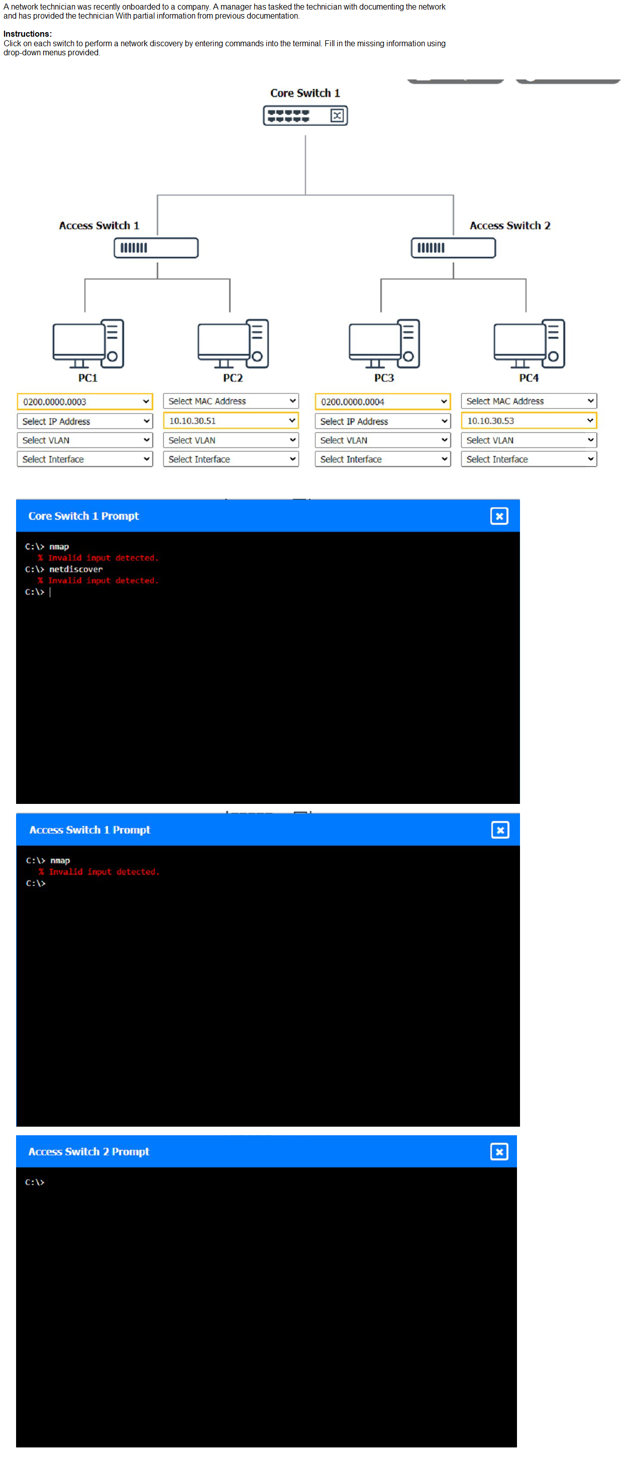
Explanation:
(Note: Ips will be change on each simulation task, so we have given example answer for the understanding)
To perform a network discovery by entering commands into the terminal, you can use the following steps:
Click on each switch to open its terminal window.
Enter the command show ip interface brief to display the IP addresses and statuses of the switch interfaces.
Enter the command show vlan brief to display the VLAN configurations and assignments of the switch interfaces.
Enter the command show cdp neighbors to display the information about the neighboring devices that are connected to the switch.
Fill in the missing information in the diagram using the drop-down menus provided.
Here is an example of how to fill in the missing information for Core Switch 1:
The IP address of Core Switch 1 is 192.168.1.1.
The VLAN configuration of Core Switch 1 is VLAN 1: 192.168.1.0/24, VLAN 2:
192.168.2.0/24, VLAN 3: 192.168.3.0/24.
The neighboring devices of Core Switch 1 are Access Switch 1 and Access Switch 2.
The interfaces that connect Core Switch 1 to Access Switch 1 are GigabitEthernet0/1 and GigabitEthernet0/2.
The interfaces that connect Core Switch 1 to Access Switch 2 are GigabitEthernet0/3 and GigabitEthernet0/4.
You can use the same steps to fill in the missing information for Access Switch 1 and Access Switch 2.
| Page 20 out of 58 Pages |